


CATEGORIES
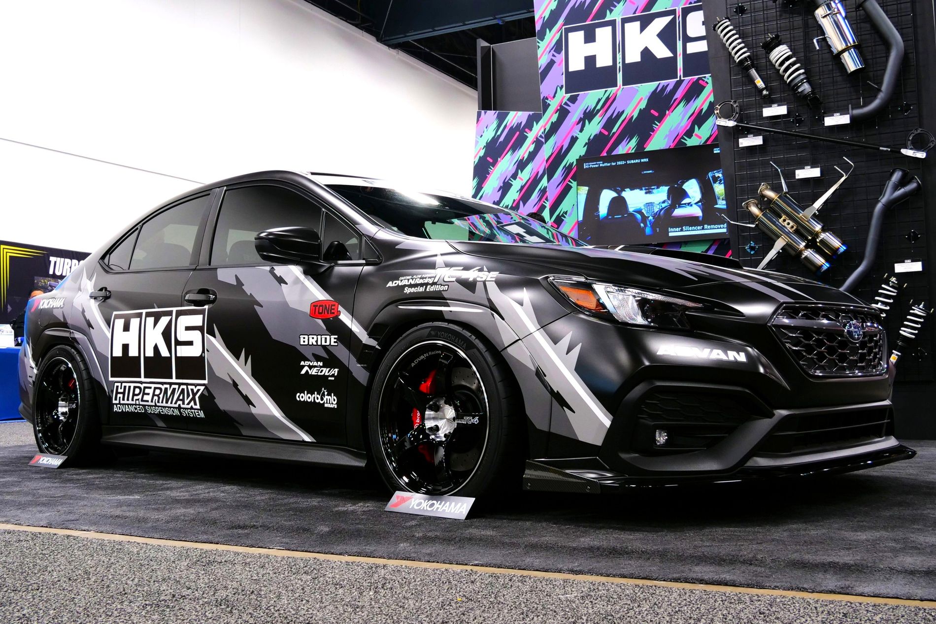
Featured Car Model
BODY KIT
HKS BODY KIT TYPE-S VBH F-Spoiler
Product Number: 53004-AF004
For: SUBARU WRX 4D (VB)
Year: 2022-2025
Engine: FA24T
MSRP: $1,350.00
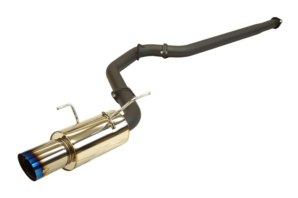
HI-POWER
Hi-Power MUFFLER Single WRX(STI) 2015 US
Product Number: 31006-BF003
For: SUBARU WRX STI 4D(VA)
Year: 2015-2021
Engine: EJ257
MSRP: $1,499.00
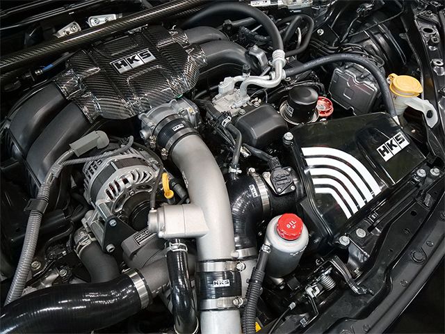
COLD AIR INTAKE KIT
GT2 S/CxCAI ADAPTER KIT ZN8/ZD8
Product Number: 12002-AT001
For: TOYOTA GR86
Year: 2022-2025
Engine: FA24
MSRP: $250.00
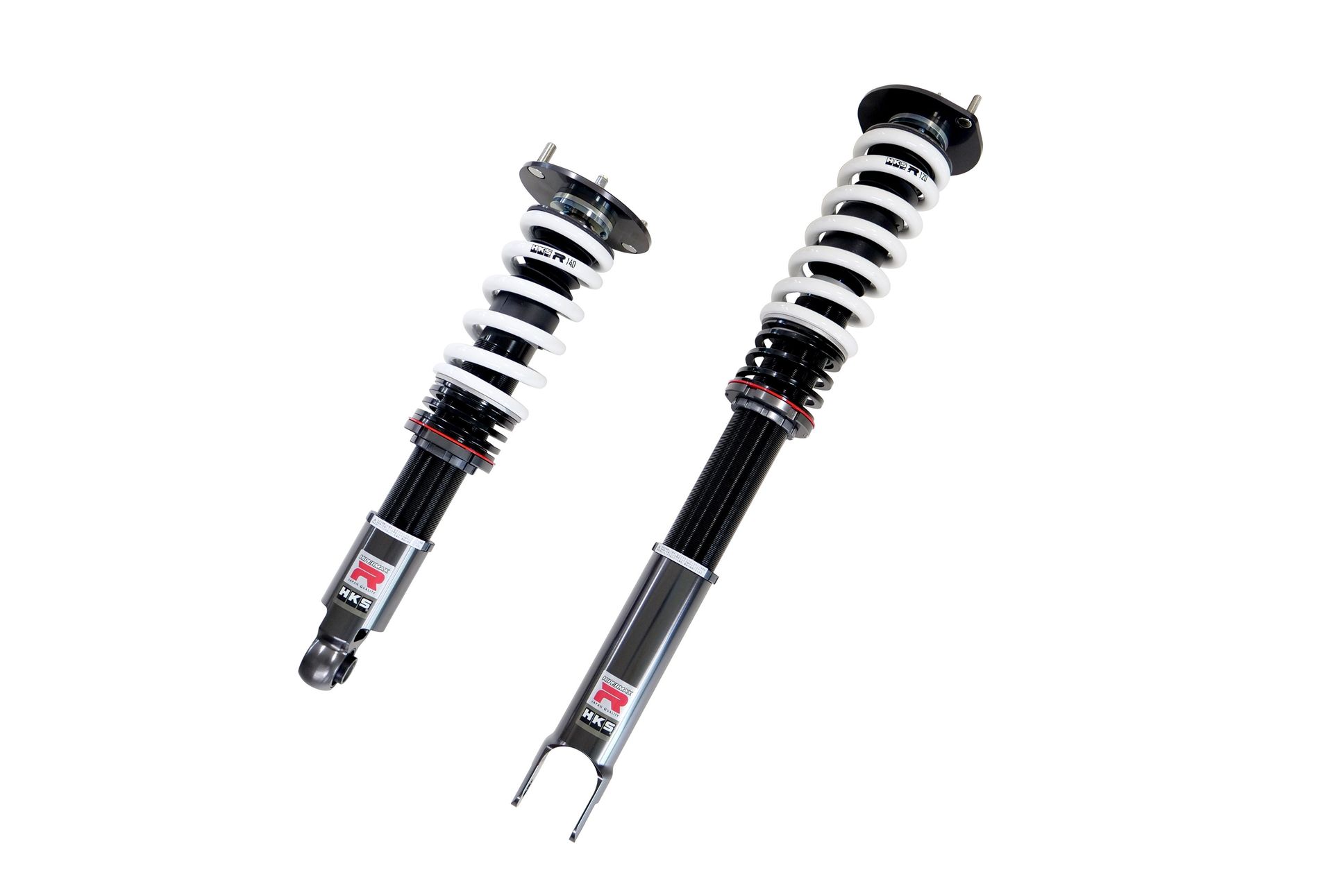
HIPERMAX R
HIPERMAX R ER34 FULL KIT
Product Number: 80310-AN008
For: NISSAN SKYLINE
Year: 1998-2001
Engine: RB25DET
MSRP: $2,990.00
HIPERMAX S
HIPERMAX S ##S13 FULL KIT F PILLOW
Product Number: 80330-AN026P
For: NISSAN SILVIA
Year: 1991-1993
Engine: SR20DET
MSRP: $2,990.00
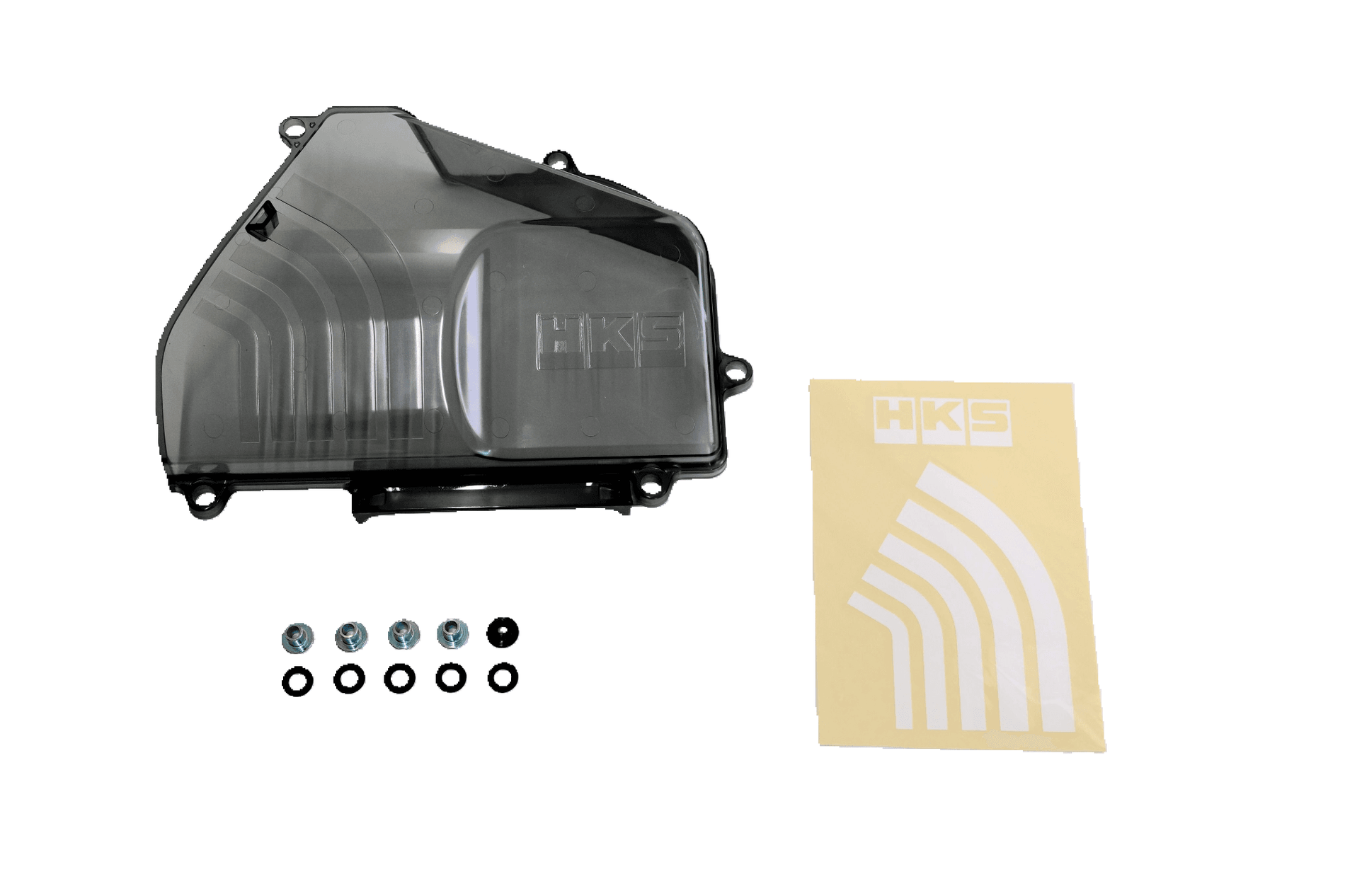
COLD AIR INTAKE KIT
COLD AIR INTAKE AIR CLEANER COVER ZN8/ZD8
Product Number: 70998-AT001
For: TOYOTA GR86
Year: 2022-2025
Engine: FA24
MSRP: $150.00
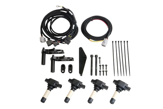
IGNITION (ELECTRONICS)
SUPER FIRE RACING COIL PRO FD3S RX-7
Product Number: 43005-AZ001
For: MAZDA RX-7
Year: 1993-2002
Engine: 13B-REW
MSRP: $1,900.00
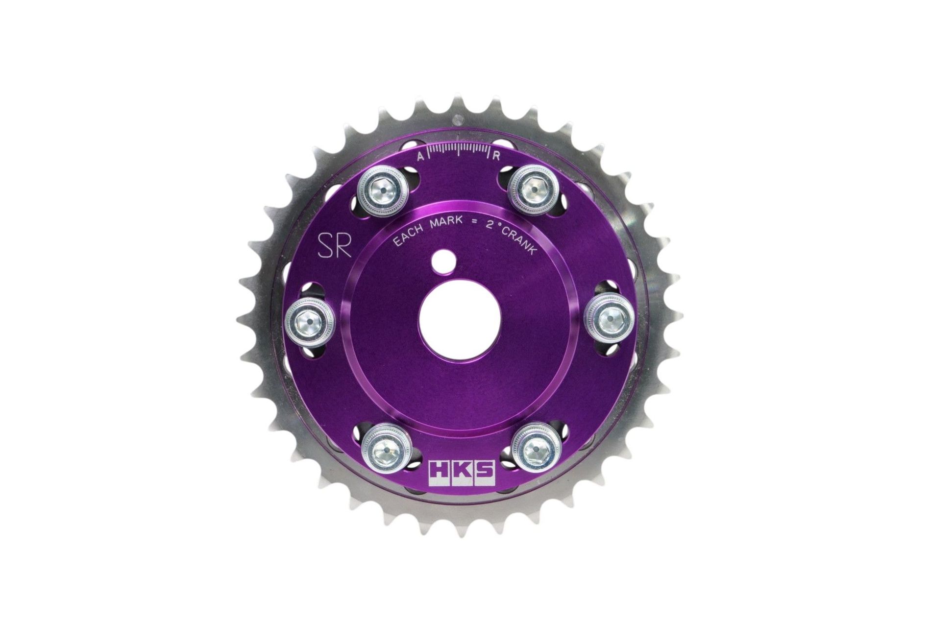
CAM PULLEY
SLIDE CAM SPROCKET SR20DE/DET INTAKE
Product Number: 22004-AN003
For: NISSAN 180SX
Year: 1991-1998
Engine: SR20DE,SR20DET
MSRP: $300.00

FULL DUAL
FULL DUAL MUFFLER Z RZ34 VR30DDTT
Product Number: 31014-KN002
For: NISSAN Z
Year: 2022-2025
Engine: VR30DDTT
MSRP: $3,400.00

LEGAMAX SPORTS
LEGAMAX SPORTS CIVIC TYPE R FL5
Product Number: 31021-AH005
For: HONDA CIVIC TYPE R
Year: 2023-2025
Engine: K20C
MSRP: $2,720.00
LEGAMAX TRAIL MASTER
LEGAMAX TRAIL MASTER 2022TUNDRA CATBACK
Product Number: 31021-BT001
For: TOYOTA TUNDRA TRD PRO
Year: 2022-2025
Engine: V35
MSRP: $2,000.00

HKSTUDIE EXHAUST
HKSTUDIE EXHAUST for BMW G80/G82 Comp
Product Number: HKSTUDIE-EX001
For: BMW M3 Sedan
Year: 2021-2024
Engine: S58B30A
MSRP: $5,500.00

HI-POWER SPEC-L
HI-POWER SPEC-L2 ZD8
Product Number: 32016-AF101
For: TOYOTA GR86
Year: 2022-2025
Engine: FA24
MSRP: $1,840.00

CAPACITY UPGRADE
I BEAM CONNECTING ROD SET FA2.1/FA2.5
Product Number: 23004-AT001
For: TOYOTA 86
Year: 2017-2020
Engine: FA20
MSRP: $1,080.00

BODY KIT
HKS BODY KIT TYPE-R FAIRLADY Z BASE KIT
Product Number: 53004-AN001
For: NISSAN Z
Year: 2022-2025
Engine: VR30DDTT
MSRP: $8,250.00

METAL HEAD GASKET
METAL HEAD GASKET FA24 T=0.8 GROMMET TYPE
Product Number: 23002-AT004
For: TOYOTA GR86
Year: 2022-2025
Engine: FA24
MSRP: $370.00
NEWS & BLOGS


VIDEO
 Introducing Our New Suspension Series - NEW HIPERMAX S -
 HKS HI-POWER MUFFLER CIVIC TYPE-R FL5 K20C (31006-KH001)
 HKS LEGAMAX SPORTS VB FA24 (31021-AF026) Install & Soundclip
 HKS LEGAMAX TRAIL MASTER 2022 TUNDRA CATBACK (31021-BT001)
 HKS GR86 & BRZ PROJECT -HKS Muffler Sound Compilation- HKSマフラー全4種 サウンド聴き比べ
 SOUND CLIPS - COMPARE - HKS A90 SUPRA HI POWER VS SUPER TURBO
 HKS Hi Power Exhaust System 600R
 Installing & Testing the HKS Full Dual Muffler on the 2023 Nissan Z – Is It Worth It?
 2023 Nissan Z Gets HKS Hipermax R Coilovers!!
 Installing HKS Coilovers on The FK8 Civic Type R
 HKS PREMIUM SALON 2021 vol.9 - NEW PARTS :TURBO -
 HKS PREMIUM SALON 2021 vol.4 - HIPERMAX S -